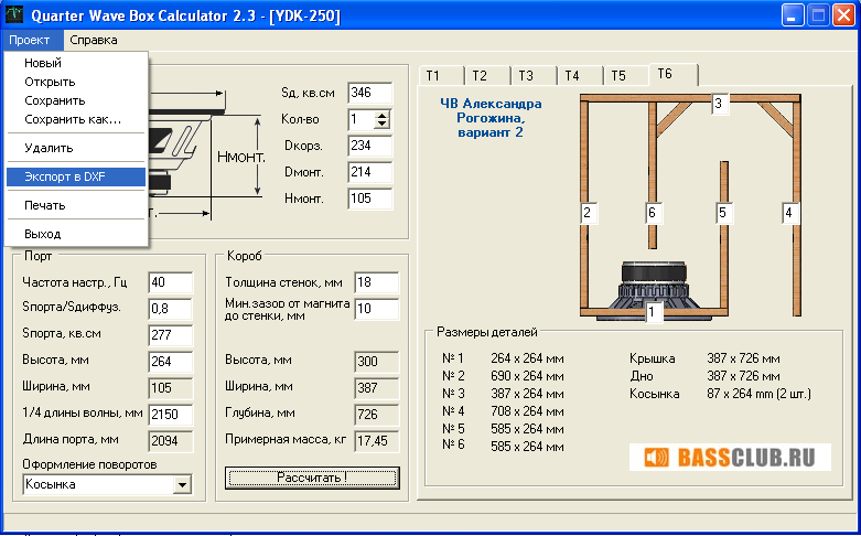
Quarter Wave Box Calculator
- 16 Comments!

1 Quarter wave box calculator 2 1 >>.
Tapered Quarter Wave Pipes EXPERIMENTS WITH TAPERED PIPES BY DAVID B. WEEMS Speaker Builder 2/87 If you run into trouble, use the line as a dog house and design either a closed box or reflex enclosure for your woofer. For champions of transmission lines who are disturbed by those frivolous words, here is a peace pipe. Or, to be more specific, a tapered pipe, like the labyrinth, the tapered pipe makes use of quarter-wave loading. Unlike the labyrinth, the driver is placed some distance from the end of the pipe. Trafaret shrifta gos nomerov na avto youtube. Tapered pipes were popular in Britain years ago, but except for a small amount of damping material behind the driver, they were bare-walled.
In fact, the de-signer of one 1960s pipe enclosure said damping material in the pipe would spoil the performance? The stuffed tapered pipe is an alter-native to those designs. Voigt was the first to use the 'stopped' pipe, which is similar in action to an organ pipe. In 1949, Ralph West developed the Decca comer speaker. Both systems had relatively small drivers.
The principle behind the pipe is shown in Figure1 The sketch in Fig. La shows relative pressure and velocity in a closed pipe at resonance. Pres-sure points occur at nodes, high velocity points at loops. If you mount a speaker at the closed end of the pipe it will be loaded by the high pressure at that end, greatly increasing efficiency. Two problems hinder this arrangement. First, the pipe's fundamental frequency is so strongly favored, low frequency performance can sound like one-note bass. Another disadvantage is odd harmonics production.
The first harmonic is the most serious, occurring at three times the fundamental's frequency Fig1c. To connect it, place the driver at one-third the distance from the pipe's stopped end Fig1d. At that point, the pressure will become somewhat lower than at the closed end, but still high enough to provide good loading at the fundamental. At the first harmonic frequency, the drive point occurs at a loop instead of a node, and output will be reduced. Voigt tapered the pipe to reduce the one-note effect and to spread the resonance over a band of frequencies Fig1e. In later versions, the throat area was reduced to zero for smoother response and the driver installed at the midpoint of the line Fig1f. More about that later, The English builders of a generation ago designed their pipes for a single-cone 8' driver.
Total cost of a driver and enclosure for one popular model was about L5, or at the rate of exchange in those days, about $14. The speaker fired upward at the rear wall so the highs dispersed around the room at a subdued level. In an attempt to restore the lost Overtones, listeners applied treble boost.
Some thought the arrangement's high frequency reproduction was inadequate. One asked, 'Who put the blanket over the cymbals?' ' The problem of highs lost in the reflection process was com-pounded by the voice coil inductance in the single-cone speaker. British builders almost always used 3/8' plywood to construct their pipes.
Thick walls were unnecessary, they said, be-cause their enclosures were stiffest at the point of greatest pressure. Some suggested using a slight degree of wall flexure because it would increase acoustic coupling near the fundamental frequency and damp air column resonances. Such statements, however, made pipe design seem more like magic or luck than science. Crack fm 2013 fix crash dump full. Everyone seemed to agree on the necessity for tight joints. One author said a 1/14' gap in the driver mounting would reduce the output at 35Hz by a factor of four.

About five years ago, after having ignored pipes because of their resemblance to the infamous 'air coupler' of early US hi-fi days, I built a pipe for a dual cone 6' x 9' car driver featuring a 10 oz. Magnet and foam suspension.
The $7 speaker had an amazing bass response in the pipe, but it also had some obvious peaks, the worst of which occurred at 95Hz and 220 Hz. The 220Hz peak was probably caused by the second harmonic, which arises at five times the pipe's fundamental frequency. A driver with a heavier magnet gave much smoother response in the 95Hz region, but showed no improvement in the higher resonance. I considered attacking the 220Hz problem with a Helmholtz resonator designed to absorb energy at that frequency, but other endeavors interrupted my plan. Recently, while digging through abandoned projects in my shop, I discovered the old pipes and wondered how the principle would work with better drivers and with damping material in the line. To save time and material, I decided to make a miniature pipe for a 4' woofer, the Radio Shack #40-1022. I knew 1 could later apply my experience to larger systems, but first, I had to design the enclosure.